
(1) MOTION SENSOR LED CONTROLLER ;
- Material ;
👉_Arduino Uno, single relay, breadboard,pir sensor,5v adaptor,ac led bulb 💡,jumper wire,

- Circuit diagram.
- How to Coding to commands 😁.

UPLOAD THE CODE ;
- #define SENSOR_PIN 2
- #define RELAY_PIN 3
- void setup()
- {
- pinMode(RELAY_PIN, OUTPUT);
- pinMode(SENSOR_PIN, INPUT);
- //Serial.begin(9600);
- }
- void loop()
- {
- //If object movement is detected then the sensor value will be 1 else the value will be 0
- int sensorValue = digitalRead(SENSOR_PIN);
- //Serial.println(sensorValue);
- if (sensorValue == HIGH)
- {
- digitalWrite(RELAY_PIN, LOW); //Relay is low level triggered relay so we need to write LOW to switch on the light
- }
- else
- {
- digitalWrite(RELAY_PIN, HIGH);
- }
- }
(2) TRAFFIC CONTROLLER CODE 3 LED ON THE Working ;
Materials Lists –
(1) 3 LED (2) Arduino uno r3 (3) Jumper wire 5 (4) 12V Adaptor 1 AMP (5) bread board 1
Upload code and the progress.
int LED1 = 13;
int LED2= 12;
int LED3= 11;
void setup() {
pinMode (LED1, OUTPUT);
pinMode (LED2, OUTPUT);
pinMode (LED3, OUTPUT);
}
void loop() {
digitalWrite (LED1, HIGH); //turn on LED1
delay(200); // wait for 200ms
digitalWrite (LED2, HIGH); //turn on LED2
delay(200); // wait for 200ms
digitalWrite (LED3, HIGH); //turn on LED3
delay(200); // wait for 200ms
digitalWrite (LED1, LOW); //turn off LED1
delay(300); // wait for 300ms
digitalWrite (LED2, LOW); //turn off LED2
delay(300); // wait for 300ms
digitalWrite (LED3, LOW); //turn off LED3
delay(300); // wait for 300ms before running program all again
}
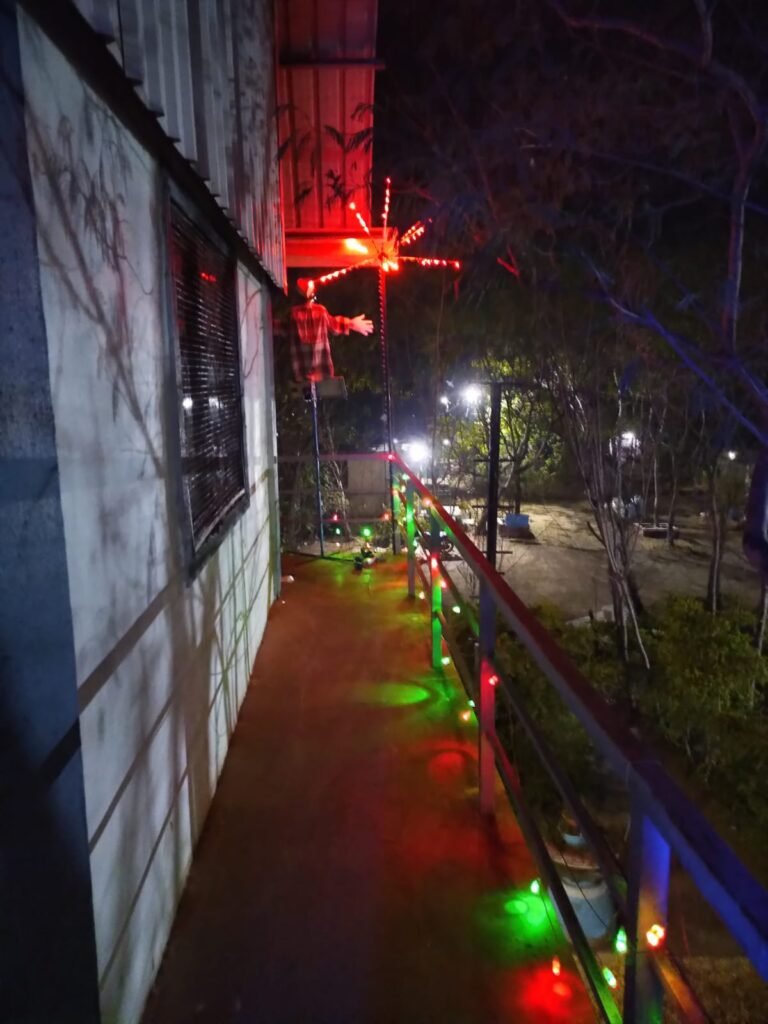
(3) FIREWORK / CRACKERS DIWALI

This project is an assistance provided for the project led by Rago sir, focusing on creating fireworks for Diwali conducted by the students.
The objective is to activate programmable LEDs to create a fireworks effect and add a sound aspect to closely resemble a real fireworks display.
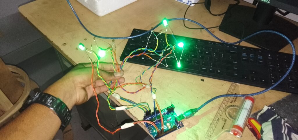
PROGRAMMING THE LEDS:
Code arduino :
This code essentially creates an animated lighting sequence on two NeoPixel rings (“fuse” of 50 led and “explosion” of 10 * 5 led in parallel), with dynamic color changes and pixel manipulations.
- Libraries Used:
Adafruit_NeoPixel: This library is used to control NeoPixel LEDs.
- Hardware Configuration:
- Two NeoPixel rings are connected to pins 11 and 12 on the Arduino.
- Additionally, there is a control pin (
pinFlancDescendant) configured to send signals to the MP3 module (see below).
- NeoPixel Initialization:
- Two NeoPixel objects (
pixelsandpixels2) are created for each ring. - The rings have sizes of 10 (
NUMPIXELS) and 50 (NUMPIXELS2) pixels, respectively.
- Two NeoPixel objects (
- Color Patterns:
- An array
colors[]holds different RGB color values. - The code cycles through these colors, applying them to the NeoPixel rings.
- An array
- Main Loop:
- The main loop iterates through each color in the
colorsarray. - For each color, a sequence of signals is sent (
HIGHandLOWstates) to the control pin. - The NeoPixel colors are set according to the current color in the loop, creating dynamic patterns on both rings.
- The lighting effect involves turning on and off specific pixels, creating a visual animation.
- The main loop iterates through each color in the
- Timing and Delays:
DELAYVALandDELAYVAL2control the delays between pixel updates for each ring.delaidefines a general delay used in the signal sending sequence.
- Pixel Updates:
- The code updates the pixels in a dynamic pattern, turning on and off specific pixels to create the desired lighting effect.
- The
previousLEDandpreviousLED1variables keep track of the previously lit pixels for smooth transitions.
- Clearing and Displaying:
- The code clears the pixel colors (
clear()) before updating them with the next pattern. - After updating the pixel colors, the
show()function is called to send the updated colors to the hardware.
- The code clears the pixel colors (
// NeoPixel Ring simple sketch (c) 2013 Shae Erisson
// Released under the GPLv3 license to match the rest of the
// Adafruit NeoPixel library

#include <Adafruit_NeoPixel.h>
#ifdef __AVR__
 #include <avr/power.h> // Required for 16 MHz Adafruit Trinket
#endif

// Which pin on the Arduino is connected to the NeoPixels?
#define PIN        11 // On Trinket or Gemma, suggest changing this to 1
#define PIN2        12 // On Trinket or Gemma, suggest changing this to 1

#define pinFlancDescendant        5

// How many NeoPixels are attached to the Arduino?
#define NUMPIXELS 10 // Popular NeoPixel ring size
#define NUMPIXELS2 50 // Popular NeoPixel ring size

// When setting up the NeoPixel library, we tell it how many pixels,
// and which pin to use to send signals. Note that for older NeoPixel
// strips you might need to change the third parameter -- see the
// strandtest example for more information on possible values.
Adafruit_NeoPixel pixels(NUMPIXELS, PIN, NEO_GRB + NEO_KHZ800);
Adafruit_NeoPixel pixels2(NUMPIXELS2, PIN2, NEO_GRB + NEO_KHZ800);

#define DELAYVAL 50 // Time (in milliseconds) to pause between pixels
#define DELAYVAL2 30 // Time (in milliseconds) to pause between pixels
#define delai 200

uint32_t colors[] = {
  //colors[k],
  pixels.Color(255, 255, 0),  // Red
  pixels.Color(0, 255, 255),  // Green
  pixels.Color(255, 0, 255),  // Blue
  pixels.Color(255, 0, 0),  // Red
  pixels.Color(0, 255, 0),  // Green
  pixels.Color(0, 0, 255),  // Blue
};


void setup() {
  // These lines are specifically to support the Adafruit Trinket 5V 16 MHz.
  // Any other board, you can remove this part (but no harm leaving it):
#if defined(__AVR_ATtiny85__) && (F_CPU == 16000000)
  clock_prescale_set(clock_div_1);
#endif
  // END of Trinket-specific code.
  pinMode(pinFlancDescendant, OUTPUT);
  digitalWrite(pinFlancDescendant, LOW);

  pixels.begin(); // INITIALIZE NeoPixel strip object (REQUIRED)
  pixels2.begin(); // INITIALIZE NeoPixel strip object (REQUIRED)

}

void loop() {
  int previousLED = 0;
  int previousLED1 = 0;

  for(int k=0; k<5; k++) { // For each pixel...
    digitalWrite(pinFlancDescendant, HIGH); // Envoyer un signal haut (flanc montant)
    delay(delai); // Attendre pendant le délai spécifié
    digitalWrite(pinFlancDescendant, LOW); // Envoyer un signal bas (flanc descendant)
    delay(delai); // Attendre pendant le même délai spécifié
        digitalWrite(pinFlancDescendant, HIGH); // Envoyer un signal haut (flanc montant)
    delay(delai); // Attendre pendant le délai spécifié
    digitalWrite(pinFlancDescendant, LOW); // Envoyer un signal bas (flanc descendant)
    delay(delai); // Attendre pendant le même délai spécifié
        digitalWrite(pinFlancDescendant, HIGH); // Envoyer un signal haut (flanc montant)
    delay(delai); // Attendre pendant le délai spécifié
    digitalWrite(pinFlancDescendant, LOW); // Envoyer un signal bas (flanc descendant)
    delay(delai); // Attendre pendant le même délai spécifié
    digitalWrite(pinFlancDescendant, HIGH); // Envoyer un signal haut (flanc montant)
       delay(delai); // Attendre pendant le délai spécifié
    pixels.clear(); // Set all pixel colors to 'off'
    pixels2.clear(); // Set all pixel colors to 'off'

    // The first NeoPixel in a strand is #0, second is 1, all the way up
    // to the count of pixels minus one.
    for(int i=0; i<NUMPIXELS2; i++) { // For each pixel...

      // pixels.Color() takes RGB values, from 0,0,0 up to 255,255,255
      // Here we're using a moderately bright green color:
      pixels2.setPixelColor(i, colors[k]);
      if (previousLED >= 5){
        pixels2.setPixelColor(previousLED - 5, pixels.Color(0, 0, 0));
      }
      pixels2.show();   // Send the updated pixel colors to the hardware.
      previousLED = i;
      delay(DELAYVAL2); // Pause before next pass through loop
    }
    pixels2.clear();
    pixels.clear();
    pixels.show();   // Send the updated pixel colors to the hardware.
    pixels2.show();   // Send the updated pixel colors to the hardware.

    for(int i=0; i<NUMPIXELS; i++) { // For each pixel...

      // pixels.Color() takes RGB values, from 0,0,0 up to 255,255,255
      // Here we're using a moderately bright green color:
      pixels.setPixelColor(i, colors[k]);
      if (previousLED1 >= 3){
        pixels.setPixelColor(previousLED1 - 3, pixels.Color(0, 0, 0));
      }
      pixels.show();   // Send the updated pixel colors to the hardware.
      previousLED1 = i;
      delay(DELAYVAL); // Pause before next pass through loop
    }
    pixels2.clear();
    pixels.clear();
    pixels.show();   // Send the updated pixel colors to the hardware.
    pixels2.show();
    for(int l=0; l<3; l++) {
      for(int i=0; i<NUMPIXELS; i++) { // For each pixel...

        // pixels.Color() takes RGB values, from 0,0,0 up to 255,255,255
        // Here we're using a moderately bright green color:
        pixels.setPixelColor(i, colors[k]);
        delay(DELAYVAL); // Pause before next pass through loop
      }

     for(int i=0; i<NUMPIXELS; i++) { // For each pixel...

        // pixels.Color() takes RGB values, from 0,0,0 up to 255,255,255
        // Here we're using a moderately bright green color:
        pixels.setPixelColor(i, pixels.Color(0, 0, 0));
        pixels.show();   // Send the updated pixel colors to the hardware.

        delay(DELAYVAL); // Pause before next pass through loop
      }
    }
  }
} 
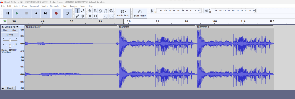
SOUND MODULES
Creation of the sound file
For sound modules, the software used includes Audacity. To achieve a fireworks-like sound, the simplest solution is to obtain MP3 sound clips directly from the internet, either from dedicated websites such as https://www.fesliyanstudios.com/royalty-free-sound-effects-download/fireworks-282, or by downloading soundtracks from YouTube videos using sites like “mp3 youtube downloader.”
Next, separate the soundtracks into clips (specific small parts) to reassemble them at the same tempo as the light effects.
The sequence consists of 3 clips: the first one representing the ascent “fuuuuuuu,” followed by the repetition of an explosion “boooomm” twice.
Mp3 module
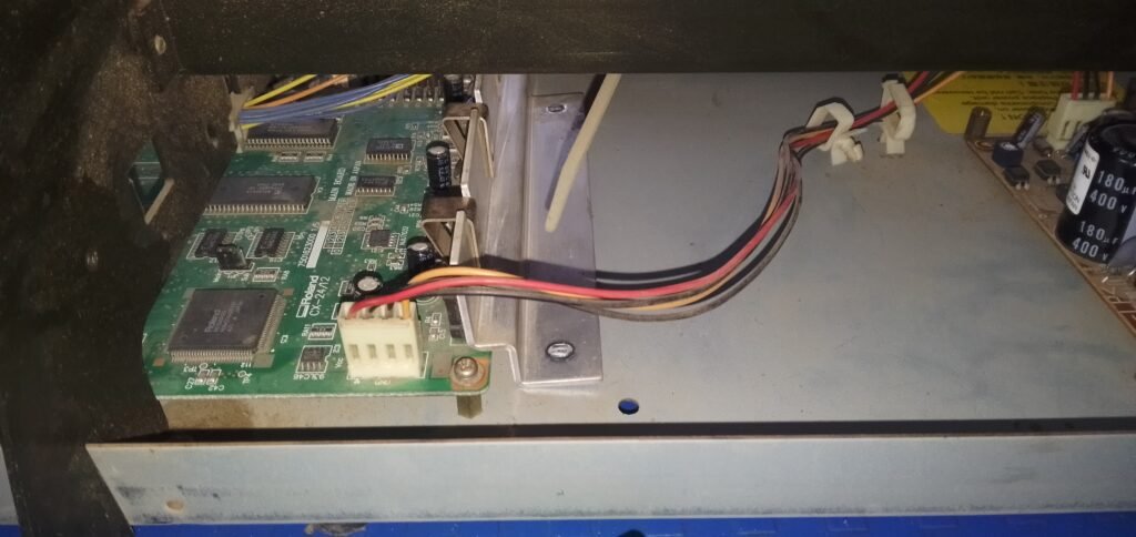
The project leveraged the sound module I created for the Smart Scarecrow project. This is why you can see the scarecrow model on the left (video below). For more information, you can refer to the details provided in the Smart Scarecrow project.
FINAL PRODUCT.

(4) SMART DUSTBIN ;
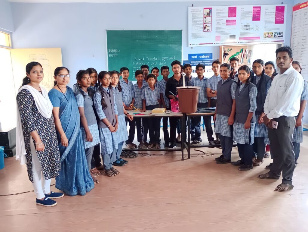

Materials lists –
(1) Servo motor (2) Plastic dustbin (3) Jumper wire 5 (4) Arduino uno (5) 12V Adaptor 1 AMP
#include <Servo.h>
Servo myservo;
int trigPin = 2; // TRIG pin of the ultrasonic sensor
int echoPin = 3; // ECHO pin of the ultrasonic sensor
long duration, cm;
void setup() {
myservo.attach(9); // Attaches the servo on pin 9 to the servo object
pinMode(trigPin, OUTPUT);
pinMode(echoPin, INPUT);
Serial.begin(9600);
}
void loop() {
// Trigger a pulse to the ultrasonic sensor
digitalWrite(trigPin, LOW);
delayMicroseconds(2);
digitalWrite(trigPin, HIGH);
delayMicroseconds(10);
digitalWrite(trigPin, LOW);
// Measure the pulse duration from the ultrasonic sensor
duration = pulseIn(echoPin, HIGH);
// Convert the duration into centimeters
cm = (duration / 2) / 29.1;
Serial.print(“Distance: “);
Serial.print(cm);
Serial.println(” cm”);
// If an object is detected within 20-40 cm, rotate the servo by 90 degrees
if (cm >= 5 && cm <= 80) {
myservo.write(180); // Rotate the servo to 90 degrees
delay(5000); // Wait for 1 second
myservo.write(0); // Rotate the servo back to 0 degrees
}
delay(1000); // Add a small delay before taking the next measurement
}
(5) UV BASED WATER PURIFICATION SYSTEM ;
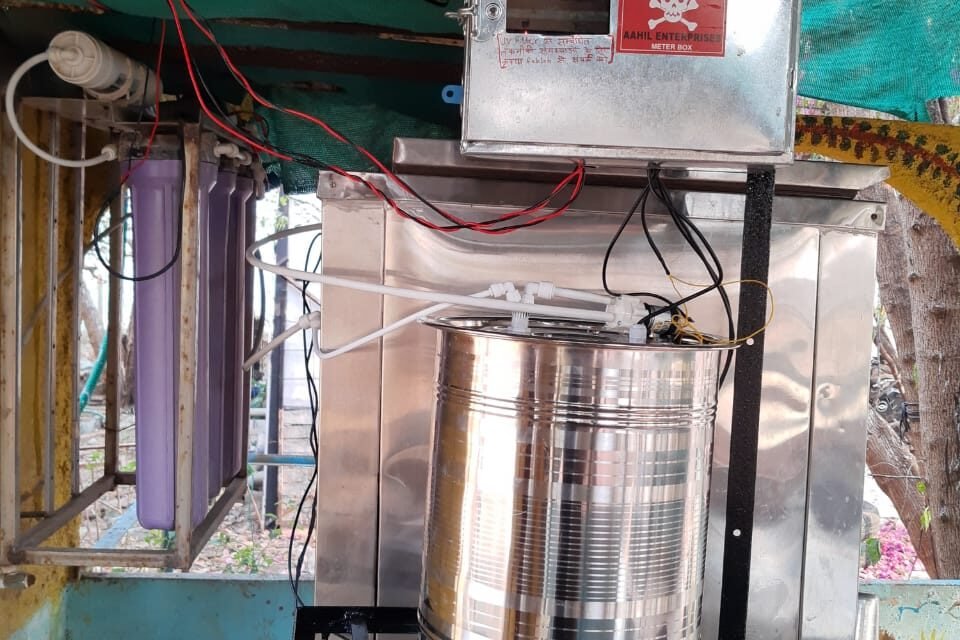
INTRODUCTION
Water is one of the essential commodities required by the human kind. Water can be obtained from various sources like groundwater: found in the ground water beds that have been filtered with soil and rocks; Surface water: artificial/ natural reservoirs, lakes, etc generally origin of rivers in the highlands; Flowing water: water obtained from rivers and canals that flow from the highlands to the oceans and seas; Artificially harvested water by technologies like atmospheric water generation, rainwater harvesting, desalination, etc. Not all the water received from these sources is potable and needs purification based on the use of the water. To purify the water, contaminants like suspended solids, organic and inorganic materials, micro-organisms, etc must be removed. Various methods are used to purify the water. Common types processes used to treat water is sedimentation, sand filtration, ultra-filtration, reverse-osmosis, chemical/UV disinfection.
OBJECTIVES
- To convert the continuous UV filtration method to batch filtration.
- To automate and optimize the complete process
- To provide micro-organism free water
PROJECT DESCRIPTION
The two most common methods of disinfecting the water from micro-organisms like bacteria is by chemical or Ultraviolet(UV) disinfection. UV light is the best to kill bacteria as it is environment friendly, chemical-free, affordable, rapid and not only acts on bacteria but also molds, fungi and a few viruses. The UV light is a electromagnetic wave present in the range 100-400 nm. It can be further divided into UV-A (315-400 nm), UV-B (280-315 nm) and UV-C (100-280 nm) . Out of the three UV-C is considered best for killing micro-organisms. The reason the UV light kills the micro-organisms is because it damages the DNA/RNA by causing a photo-chemical reaction in thymine/cystine (DNA) and uracil (RNA) dimers. The change in the genetic material lead to mutation and finally results into the death of the cells. Using this principle a automated system for purification of water was developed in continuation of the previous efforts at Vigyan Ashram . This system will disinfect the water by ultraviolet light in a batch process as opposed to the traditional continuous method. The water is filtered in batches in a small container and then added to a large container for storage. The system uses float switches to automatically cut-off the the water supply to the containers. The following flowchart best explains the working of the system.
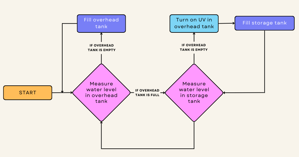
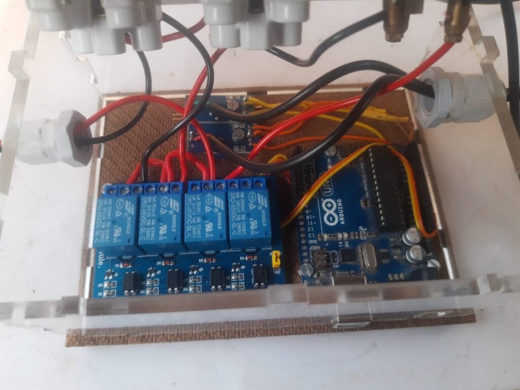
DEVELOPMENT OF THE PROJECT
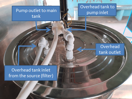
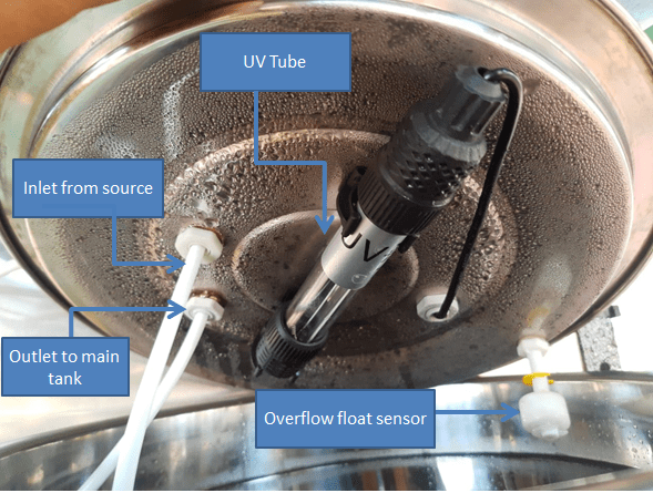
The whole system works on an Arduino UNO microcontroller. The Arduino UNO is connected to 2 float sensors and a multichannel relay. The relay regulates flow of AC supply to 2 motors and 1 UV tube. The float sensors avoid overflow of water from the tanks. The relay receives signal based on the float sensors activate or deactivate the motors that fill each of the two tanks along with the UV tube that disinfects the water in the overhead tank for 10 minutes. The electronic system is housed in a laser cut casing made out of MDF and acrylic sheets. In order to design the solution, a stainless steel vessel was used as an overhead tank. which would get water from the source and store for disinfection in a batch process. Initially solenoid valves we attached to these vessels in order to control the water flow. The solenoid valve required pressure to operate and took 25-30 minutes to empty the vessel completely. To increase the speed a submersible motor was tested. The motor would act as a storage for bacteria if submerged in the water and UV would not be very effective. This motor was unable to pull water to a height so it was connected to the end of solenoid valve in order to pull the water from the solenoid by increase the pressure on the solenoid valve. This arrangement reduced to time to empty the vessel to 14 minutes. This arrangement consumed more power due to two devices being utilized simultaneously. To solve the above problems, a non-submersible pump was tested. This pump could pull water up to 2 meters and push the water up to 3 meters. The pump was connected on top of the overhead vessel. This pump was able to empty the vessel in 8-10 minutes. This pump was chosen for he final design with white pipes instead of transparent pipes to avoid fungal growth due to sunlight. The system was deployed and water was tested.
IMPROVEMENTS REQUIRED
- The system needs to be more compact and easy to install
- The electronic component should be made on a PCB
- Optimization of the time for disinfection.
Code
int motor = 2;
int UV = 3;
int solenoid = 4;
int f1 = A1;
int f2 = A0;
int lvl1 =1;
int lvl2 =1;
int count = 0;
bool activate = LOW;
bool deactivate = HIGH;

void setup()
{
  pinMode(motor, OUTPUT);
  pinMode(UV, OUTPUT);
  pinMode(solenoid, OUTPUT);
  digitalWrite(motor, deactivate);
  digitalWrite(solenoid, deactivate);
  digitalWrite(UV, activate);
  delay(1000);
  digitalWrite(UV, deactivate);
  Serial.begin(9600);

}


void loop()
{
  lvl1 = digitalRead(f1);
  lvl2 = digitalRead(f2);
  delay(1000);
  if(lvl2 == 0)
  {
    //Fill the over head tank
    overhead();
    //sterilize water
    sterilize();
    while(count<3)
    {
      if(lvl2 == 0)
      {
        digitalWrite(solenoid, activate);
        delay(120000);
        digitalWrite(solenoid, deactivate);
        lvl2 = digitalRead(f2);
        delay(500);
      }
      count++;
    }
    count = 0;
  }
}

void overhead()
{
  Serial.println(lvl1);
  digitalWrite(solenoid, deactivate);
  while(lvl1 == 0)
    {
      digitalWrite(motor, activate);
      lvl1 = digitalRead(f1);
    }
  digitalWrite(motor, deactivate);
}

void sterilize()
{
  digitalWrite(UV, activate);
  delay(600000);
  digitalWrite(UV, deactivate);
  delay(1000);
}
(6) GANPATI ASHIRVAAD PROJECT ;
MATERIAL LIST-
(1) SERVO MOTOR ,(2) ULTRASONICS SENSOR (3) 5V ADPTER, (4) CASION BOARD,(5) PIPE 1FEET.

UPLOAD CODE AND THE PROGRESS ;
#include <Servo.h>
#define trigPin 7
#define echoPin 6
Servo servo;
void setup()
{
Serial.begin (9600);
pinMode(trigPin, OUTPUT);
pinMode(echoPin, INPUT);
servo.attach(8);
}
void loop()
{
long duration, distance;
digitalWrite(trigPin, LOW);
delayMicroseconds(2);
digitalWrite(trigPin, HIGH);
delayMicroseconds(10);
digitalWrite(trigPin, LOW);
duration = pulseIn(echoPin, HIGH);
distance = (duration/2) / 29.1;
if (distance < 15)
{
Serial.println(“the distance is less than 5”);
servo.write(120);
}
else
{
servo.write(0);
}
if (distance > 60 || distance <= 0)
{
Serial.println(“The distance is more than 60”);
}
else
{
Serial.print(distance);
Serial.println(” cm”);
}
delay(500);
}
(7) GIRLS HOSTEL TANK ;
Materials List-
(1) Arduino uno (2) 5v Adptor (3) Buzzer (4) Single relay (5) Float sensor (6) Casion box (7) 2 core wire 1 mtr.
Hardware Use :

Upload code and progress.
/*
Button
Turns on and off a light emitting diode(LED) connected to digital pin 13,
when pressing a pushbutton attached to pin 2.
The circuit:
– LED attached from pin 13 to ground
– pushbutton attached to pin 2 from +5V
– 10K resistor attached to pin 2 from ground
– Note: on most Arduinos there is already an LED on the board
attached to pin 13.
created 2005
by DojoDave <http://www.0j0.org>
modified 30 Aug 2011
by Tom Igoe
This example code is in the public domain.
http://www.arduino.cc/en/Tutorial/Button
*/
// constants won’t change. They’re used here to set pin numbers:
const int buttonPin = 2; // the number of the pushbutton pin
const int ledPin = 13; // the number of the LED pin
// variables will change:
int buttonState = 0;
//int buttonPin =0;
int x =1;
void setup() {
// initialize the LED pin as an output:
pinMode(ledPin, OUTPUT);
// initialize the pushbutton pin as an input:
pinMode(buttonPin, INPUT_PULLUP);
}
void loop() {
// read the state of the pushbutton value:
buttonState = digitalRead(buttonPin);
// check if the pushbutton is pressed. If it is, the buttonState is HIGH:
if (buttonState == LOW && x==1)
{
digitalWrite(ledPin, LOW);
delay(500);
digitalWrite(ledPin, HIGH);
delay(500);
digitalWrite(ledPin, LOW);
delay(500);
digitalWrite(ledPin, HIGH);
delay(500);
digitalWrite(ledPin, LOW);
delay(500);
digitalWrite(ledPin, HIGH);
x=0;
} else if (buttonState == HIGH && x==0)
{
digitalWrite(ledPin, HIGH);
x=1;
}
else{
digitalWrite(ledPin, HIGH);
}
}
(8) NAME PLATE DISPLAY BOARD ;
(1) Arduino uno (2) 12V Adptor-2 (3) Single relay (4) LED Light pattern (5) LDR Sensor(6) Casion box (7) Ultrasonics sensor.
Explain- lets it see.
Here’s a basic Arduino code for you, which uses an LDR (Light Dependent Resistor) sensor to control the LED light at night, and an ultrasonic sensor for distance measurement, along with a single relay. Keep in mind that you will have to connect the LDR sensor and ultrasonic sensor correctly, and customize the code according to your hardware configuration.
Upload code And the progress.
const int ldrPin = A0; // LDR sensor pin connected to A0
const int trigPin = 9; // Ultrasonic sensor trig pin connected to digital pin 9
const int echoPin = 10; // Ultrasonic sensor echo pin connected to digital pin 10
const int relayPin = 8; // Single relay control pin connected to digital pin 8
const int ledPin = 7; // LED pin connected to digital pin 7
void setup() {
pinMode(ldrPin, INPUT);
pinMode(trigPin, OUTPUT);
pinMode(echoPin, INPUT);
pinMode(relayPin, OUTPUT);
pinMode(ledPin, OUTPUT);
Serial.begin(9600);
}
void loop() {
int ldrValue = analogRead(ldrPin);
float distance_cm = measureDistance();
if (ldrValue < 500) { // Adjust this threshold based on your LDR sensor readings
digitalWrite(relayPin, HIGH); // Turn on the relay
digitalWrite(ledPin, HIGH); // Turn on the LED
} else {
digitalWrite(relayPin, LOW); // Turn off the relay
digitalWrite(ledPin, LOW); // Turn off the LED
}
Serial.print(“LDR Value: “);
Serial.println(ldrValue);
Serial.print(“Distance (cm): “);
Serial.println(distance_cm);
delay(1000); // Delay for 1 second
}
float measureDistance() {
digitalWrite(trigPin, LOW);
delayMicroseconds(2);
digitalWrite(trigPin, HIGH);
delayMicroseconds(10);
digitalWrite(trigPin, LOW);
long duration = pulseIn(echoPin, HIGH);
float distance_cm = duration * 0.0343 / 2;
return distance_cm;
}
(9) WATER OVERFLOW SYSTEM ;
Problem Statement :
Tank water overflow is a common issue that many households, businesses, and industries face, which can cause water wastage. The overflow of tank water occurs due to various reasons, including improper tank installation and irregular maintenance. Therefore, there is a need for an automated system that can detect the water level in the tank and alert the users before it overflows.
Hardware Use :
IF YOU WANT TO BUY CLICK ON THE SHOPPING LINK 👇👇
| sr.no | Product Name | Nos. | Shopping Link |
| 1 | Timing Delay Switch Controller | 1 | Robu.in |
| 2 | 12v Siern | 1 | Robu.in |
| 3 | Float Sensor | 1 | Electronicomps.com |
| 4 | Junction Box | 1 | Amozon.in |
| 5 | female Dc Power Jack | 1 | Electronicomps.com |
| 6 | 12v Adapter | 1 | Amozon .in |
HOW DO FLOAT SENSORS WORK ??

To put it simply, a float switch is a mechanical switch that floats on the surface of a liquid. The float switch moves vertically up and down as the liquid level changes.

When the magnet is close to the reed switch, an electrical current can flow through, and close the circuit, signaling to the controller on alarm.
HOW TO SET A TIME ?? SEE THIS VIDEO 👇👇
Circuit Diagram :

DO SHOULDER FOR CONNECTION FIX. ASSEMBLE IN THE JUNCTION BOX

PROPER SEE WIRRING USE CABLE GLAND

ASSEMBLY LIKE THIS 👇👇

PUT IT WHERE THE TANK COMES TO FILL BECAUSE YOU CAN TURN OFF THE MOTOR WHEN THE ALARM GOES OFF.
Video :
(10) STREET LIGHT CONTROLLER ;
Materials Lists-
(1) Arduino uno (2) single relay (3) LDR Sensor (4) jumper wire (m to f -5) (5) 5V adptor (6) Casion box (7)
Upload code and the progress ;
const int ldrPin = A0; // LDR sensor pin connected to A0
const int relayPin = 8; // Single relay control pin connected to digital pin 8
const int ledPin = 7; // LED pin connected to digital pin 7
void setup() {
pinMode(ldrPin, INPUT);
pinMode(relayPin, OUTPUT);
pinMode(ledPin, OUTPUT);
Serial.begin(9600);
}
void loop() {
int ldrValue = analogRead(ldrPin);
if (isNight(ldrValue)) {
digitalWrite(relayPin, HIGH); // Turn on the relay
digitalWrite(ledPin, HIGH); // Turn on the LED
} else {
digitalWrite(relayPin, LOW); // Turn off the relay
digitalWrite(ledPin, LOW); // Turn off the LED
}
Serial.print(“LDR Value: “);
Serial.println(ldrValue);
delay(1000); // Delay for 1 second
}
bool isNight(int ldrValue) {
// Adjust this threshold based on your LDR sensor readings
// Smaller values mean darker conditions
return ldrValue < 500;
}
Code Explained …………
In this code, the readings from LDR sensor are used by isNight function. If LDR value is less than 500, then the code will be considered at night, and the relay and LED light will turn on. If LDR value is 500 or more, then the code will be considered, and the relay and LED light band will be activated.
(11) CURD MAKER MACHING..
CURD MAKING MACHING / DAHI MAKING MACHINE / YOGURT MAKING MACHINE / EGG INCUBATOR / HOT AIR OVEN
INTRODUCTION
Curd, also known as yogurt, is a versatile and nutritious dairy product that has been consumed for centuries. It is made by fermenting milk with the help of bacteria, which convert the lactose in milk into lactic acid, giving curd its distinctive tangy taste and creamy texture. Making curd at home is not only cost-effective, but it also allows you to control the quality and freshness of the ingredients.
PROBLEM STATEMENT
While making curd at home or kitchen is a relatively straightforward process, there are a few common problems that you may encounter such as Curd not setting, Curd turning out sour or overly tangy, Curd turning out too thin or watery, Contamination or spoilage.
SOLUTION:-
To overcome the challenges of making curd at home and ensure high-quality, consistent results every day, we have developed a state-of-the-art curd maker with an impressive capacity of 25 liters. Our innovative curd maker is not only designed to make the curd-making process a breeze, but it is also energy-efficient, minimizing your environmental impact while maximizing your culinary success.
Curd making machine is the best invention for the dairy farms, Mega Kitchen, Hotels and Food Processing units as this machine can help the end user to make the curd instantly.
This machine has the inbuilt container with different capacities and the long electronic cord that automatically gets heat-up and maintain the equilibrium condition suitable for Good bacteria growth in order to produced Curd from Milk. It is amazing product and have capacity for making curd in large quantity in the hygienic conditions, lesser time along with retaining its quality.
LETS SEE HOW TO MAKE A CURD MAKER:-
Material Required:-
- Insulated Ice Box 65 L Capacity
- Immersion Water Heater
- Temperature Controller
- Gen Pan 25L for Storing Curd


Step 1:- Take a insulated ice box 65 liters capacity
Step 2:- Mark the hole for mounting heater on the side wall of Box and Cut the hole with the help of drill machine

Step 3:- Connect the Heater with proper insulation and sealing agent with the wall of Heater.
Step 4:- Now Put the Gen Pan in the Compartment and mark the point where its border match with the wall of Box, so that we can attach the tray holder.
Note:- While purchasing the Gen Pan verify whether it fits properly in the Ice Box.
It is recommended to purchase a Stainless Steel Food Grade Pan to avoid metal reaction within the compartment.
Step 5:- Made the connection of the heater with temperature controller and Test It
Step 6:- Set the Temp of the controller at 40 degree Celsius. The procedure for setting the the controller is provided in this link https://www.youtube.com/watch?v=3MCT39XUlo0

Step 7:- Insert the Thermocouple inside the Compartment by drilling a hole, and mount the sensor near the gen pan mounting.

Your system is now ready it will look like this after completing all the connections.

(12) IDLI MAKER MACHING CONTROLLER ..
Materials –
(1) FRONTIERS TIMER (2) 1.5 MM 4 WIRES
Frontiers timer will start only on Thursday of the week at 6 am and will stop at 9 pm. By doing this, I set the timer to match the idli maker.
SET TIME-
THURSDAY -MORNING =6:00AM TO 9:00 AM
(13) SMART TIME………
In traditional events we have used samai to Deep-Prajwalan .For example in school or college for inauguration events use samai that requires oil,cotton,Magic-sticks. Instead of this samai we can use “Smart Samai” which is lighting with the help of a mobile torch.
Step 1: Required Material
List of material:- 1) Arduino Uno Board- 1 , 2) LDR(Light dependent resistor)- 5 ,3) LED(Light emitting diode)- 5 (white color LED) ,4) Resistor- 5 (1 Kilo-ohm) , 5) Connecting wire( multi strand)- 5 meter ,6)Plastic Samai- 1 ,7) 9V Adaptor- 1
Step 2: Working Principle of LDR

In Electronics Samai uses an LDR sensor (Light Dependent Resistor) as an input which is dependent on natural light. This natural light is measured by using a lux meter. Value of normal natural light at 10am is 300 Lux to 500 Lux.(value depends on sunlight).
A Light Dependent Resistor (LDR) is also called a photoresistor or a cadmium sulfide (CdS) cell. It is basically a photocell that works on the principle of photoconductivity. LDR’s are light dependent devices whose resistance is decreased when light falls on LDR and resistance is increased when LDR is in the dark.
Step 3: Let’s Make the Smart Samai Connection

We required 5 LDR, 5 Resistor, 5 white color LED for one samai .
- First step is take 1 LDR which second terminal connect to the first terminal of resistor and second terminal of resistor connect with negative terminal( cathode) of LED with help of soldering material by using soldering gun.
- After that connect four wires – 2 are red colored, 2 are black colored. The first red wire connects to the first terminal of the LDR, and the second red wire connects to the positive terminal ( Anode) of the LED.
- Both black wires connect to the both terminals of the resistor as shown in the above image. 1 resistor, 1 LED that are connected with each other with the help of soldering material and soldering gun as shown in image. After that, the soldering part is covered with insulating material(cellotape).
Step 4: Connecting With Arduino
- Coding lets go to see;
int sensorPin1 = A0;// select the input pin for ldr
int sensorPin2 = A1;// select the input pin for ldr
int sensorPin3 = A2;// select the input pin for ldr
int sensorPin4 = A3;// select the input pin for ldr
int sensorPin5 = A4;// select the input pin for ldr
int sensorValue = 0; // variable to store the value coming from the sensor
void setup() {
pinMode(2, OUTPUT); //pin connected to LED
pinMode(3, OUTPUT); //pin connected to LED
pinMode(4, OUTPUT); //pin connected to LED
pinMode(5, OUTPUT); //pin connected to LED
pinMode(6, OUTPUT); //pin connected to LED
Serial.begin(9600); //sets serial port for communication
}
void loop() {
sensorValue = analogRead(sensorPin1);
Serial.println(sensorValue); //prints the values coming from the sensor on the screen
if(sensorValue > 900) //setting a threshold value
digitalWrite(2,HIGH); //turn LED ON
sensorValue = analogRead(sensorPin2);
Serial.println(sensorValue); //prints the values coming from the sensor on the screen
if(sensorValue > 900) //setting a threshold value
digitalWrite(3,HIGH); //turn LED ON
sensorValue = analogRead(sensorPin3);
Serial.println(sensorValue); //prints the values coming from the sensor on the screen
if(sensorValue > 900) //setting a threshold value
digitalWrite(4,HIGH); //turn LED ON
sensorValue = analogRead(sensorPin4);
Serial.println(sensorValue); //prints the values coming from the sensor on the screen
if(sensorValue > 900) //setting a threshold value
digitalWrite(5,HIGH); //turn LED ON
sensorValue = analogRead(sensorPin5);
Serial.println(sensorValue); //prints the values coming from the sensor on the screen
if(sensorValue > 900) //setting a threshold value
digitalWrite(6,HIGH); //turn LED ON
}
- DIAGRAM

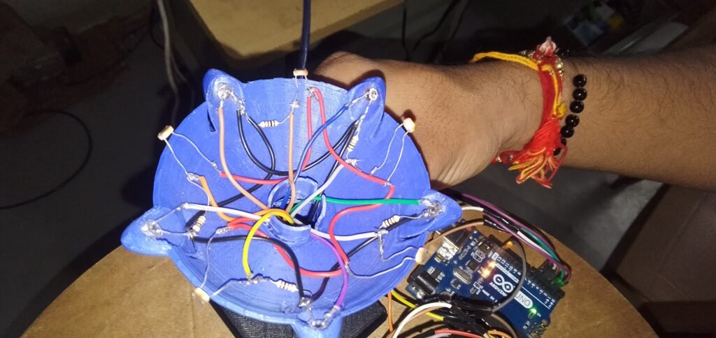
(14) SMART SCARECROW – UPDATED.
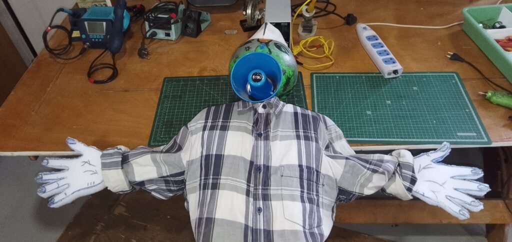
Introduction;
This project is a continuation of the work done by XXX, which you can find at the following link: [insert link here]. The main goal of this project is to improve the current scarecrow design to prepare it for future commercialization.
THE PROJECT: A TWO-PART ENDEAVOR
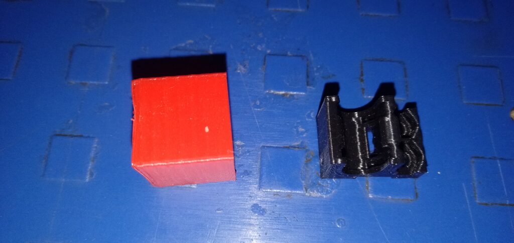
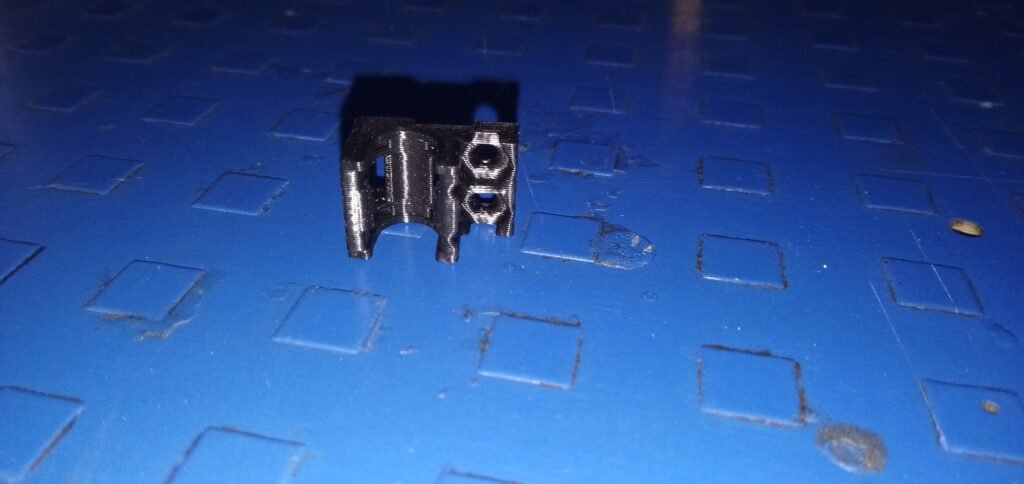
- Strengthening the Structure: We aim to make the scarecrow more resilient by developing a 3D printed part that connects the pole to the body of the scarecrow.
- Affordability and Commercial Viability: We are also working to make the product more affordable and market-ready by creating a PCB (Printed Circuit Board) that consolidates all the necessary electronic functions.
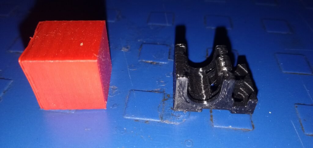
PART I: 3D PRINTING
The objective here is to create a modular and adaptable piece that can withstand the forces exerted on the scarecrow due to strong wind movements in the fields. You can view the finished piece and associated plans here.


A final version has been updated to include a hole in the pole for screwing purposes and a slight elongation of the two arms to increase resistance.

All parts and plans are available on the following GitHub repository: [insert link here].
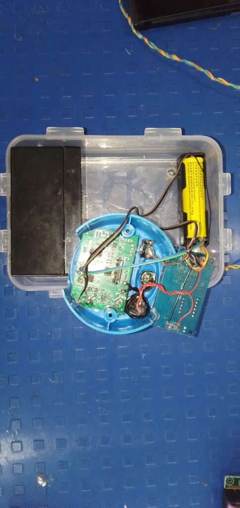
PART II: ELECTRONICS
The current system relies on commercially available parts that require assembly. These parts have more functionality than needed for the scarecrow, which is why we decided to create our own PCB that consolidates all these functions, reducing costs and increasing the product’s longevity.
Previous Model Overview:

Two main electronic functions need to be realized:
- Economical Timer: To control the scarecrow’s movements.
- Economical Sound System: For our product.
a. Economical Timer: Based on the NE555 module, which is particularly interesting for fixed-time systems. It only requires two resistors and a capacitor to operate. We use the Timer555 in its astable mode (see diagram) more information on this device in this tutorial.

The choice of resistors and capacitor is based on the following formulas:
T = 0.693 *( R1 + R2) *C : Time High
T = 0.693 * R2 * C : Time Low
To simplify, you can use the following website to get direct values for a given pair (R1, R2, C1): link.
In our case, for a total operation of X minutes and Y minutes of movement, the resistances R1, R2, C1 are equal to ().
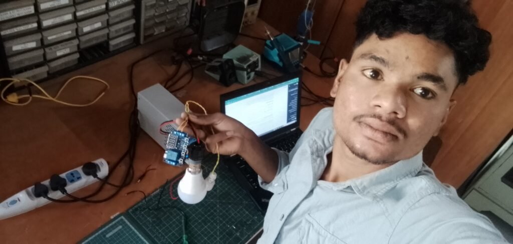
Premier test realise avec jumper et alim de labo :
b. Economical Sound System: Requires two new components: an MP3 module and an amplifier.
The MP3 module retrieves sound from an SD card and converts it into a signal that the speaker can understand. However, as the output signal is too weak, an amplifier is added to increase the sound signal’s power from the MP3.
The new system thus includes these components (see Figure X).

Module used
MP3 : datasheet
Ampli : datasheet
PART 3 PRICE COMPARISON:
Old version material cost: [insert cost here].
| Old version | |
| Music | |
| Timer | 250 Rs |
| Total |
New version material cost (including PCB): [insert cost here].
| New version | |
| MP3 module | 100 Rs |
| Amplifier | 95 Rs |
| Ne555 | 19 Rs |
| Relay | 55 Rs |
| Resistor (9MOhm & 1MOhm) | 10 Rs |
| Capacitor (1000uF) | 15 Rs |
| Total | 294 Rs (195+99) |
This results in savings of X Rs.
PART 4 CREATING A PCB:
Finally, we need to create a PCB that brings all these components together into a single module.
The PCB plans will be available here soon: [insert link when ready].
Timer pcb part :


HERE’S A LIST OF THE NECESSARY COMPONENTS WITH THEIR NAMES, PRICES, QUANTITY, AND SUPPLIER LINKS: [INSERT LIST HERE].
| New version | Price | Quantity | Supplier link |
| MP3 module | 100 Rs | 1 | https://robu.in/product/mp3-tf-16p-mp3-disk-tf-card-module-serial-port/ |
| Amplifier | 95 Rs | 1 | https://robu.in/product/tda2030a-6-12v-18w-audio-amplifier-module/ |
| Ne555 | 19 Rs | 1 | https://robu.in/product/ne555dr-texas-instruments-precision-timer-ic-timing-microseconds-to-hours-ttl-astable-monostable-4-5-v-to-16-v-soic-8/ |
| Relay | 55 Rs | 1 | https://robu.in/product/12v-1-channel-relay-module/ |
| DC motor | 1 | ||
| Resistor (9MOhm & 1MOhm) | 5/5 Rs | 1/1 | https://robu.in/product/10m-ohm-1-4w-0603-surface-mount-chip-resistor-pack-of-100/https://robu.in/product/1m-ohm-1-4w-0603-surface-mount-chip-resistor-pack-of-100/ |
| Capacitor (1000uF) | 15 Rs | 1 | https://robu.in/product/1000uf-25v-electrolytic-capacitor-dip-pack-of-5/ |
| Switch ON/off | 1 | ||
| Speaker | 1 | ||
| Pcb itself | 1 | ||
| Total |
(15) MAKERPI 3D PRINTER
INTRODUCTION :
1. There was a problem with the printer and I solved it.
1.Clips 2.Bed leveling 3.Extruder problem 4.power Jack 5.
Clips Exchange 💱….


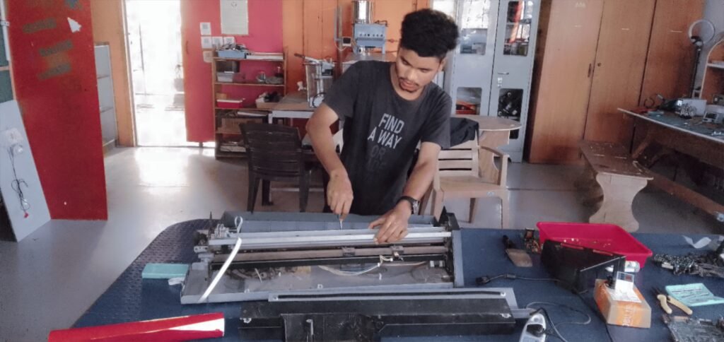
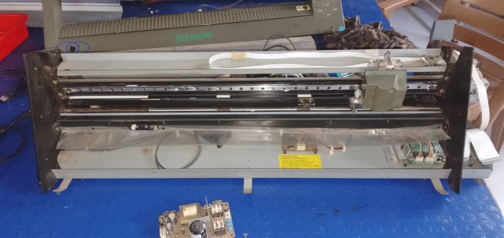
(16) VINYLE CUTTER MACHINE REPAIRING.
WARNING INTRODUCTION :
1.Problems
- Mother boards exchange 2.power supply board exchange.
- Mostly come on out sensor error..

(17) Tropical design laser in the.
(18) ULTRASONICS SENSOR AND AC LED LIGHT MOTION CONTROLLER TYPE .
Materials list – ultrasonics sensor and single relay ya doubble relay LED 3 in one ,AC light ,wire .
UPLOAD THE CODE AND THE PROGRESS..
// Include necessary libraries
#include <NewPing.h>
// Define ultrasonic sensor pins
#define TRIGGER_PIN 9
#define ECHO_PIN 10
#define MAX_DISTANCE 200 // Maximum distance in cm, adjust based on your sensor’s specifications
// Define LED pin
#define LED_PIN 13 // Replace with the actual pin number you are using for the LED
// Create an instance of the NewPing class
NewPing sonar(TRIGGER_PIN, ECHO_PIN, MAX_DISTANCE);
void setup() {
// Initialize LED pin as OUTPUT
pinMode(LED_PIN, OUTPUT);
}
void loop() {
// Get the distance from the ultrasonic sensor
int distance = sonar.ping_cm();
// Check if the distance is within a certain range (e.g., 50 cm)
if (distance > 0 && distance <= 80) {
// Turn on the LED for 2 minutes (120,000 milliseconds)
digitalWrite(LED_PIN, LOW);
delay(5000);
// Turn off the LED for 2 minutes (120,000 milliseconds)
digitalWrite(LED_PIN, HIGH);
delay(100);
}
// You can add additional conditions or actions based on different distance thresholds
// For example:
// if (distance <= 60) {
// // Do something else
// }
// Add a small delay for stability
delay(4);
}
(19) CNC WOOD ROUTER MACHINE OPERATION.
OPERATING STEP BY STEP…
Art Cam PRO 9.1 MACHINE
- First open ArtCAM Software open karo…
- Uske baad create new model ka option per click karo..
- Apki machine ki hisab se height aur width ko measure (mm/cm) dedo okay aur ap design graph hai aur uske baad (ok.. click karo )…..
- Basically Design karo..( Vector tools ) bolke lika hua hai < ishme jao Aur Create rectangle mein click karo Aur bahut sare safe ki design mile ga..>………< Aur usme se mein circle liya click karke.
- Circle creation ke aaya hai…
- < X/Y > ka measurement dedo 40 by 40( circle size pe ) Diameter bhi 40 dena okay. Aur niche scroll karke jane ka…..Aur (create pe click karna okay – baad mein close click karna)..
- Sabse niche jana hai toolpaths pe click karna hai..
- 2D toolpaths jana hai aur pehla wala ko cutting keliye mein select kiya ( profiling likha hai )
- Profiling ki upar aata hai,,aur niche ana hai ( Profile side OUTSIDE CLICK ….Start depth ko 1 dena ,Finish depth ko 4 aur niche scroll karke jana hai ( profiling tool pe select pe click karna hai..aur uske baad tool group nikal tha hai ,roughing and 2d finishing per hee,,End mill 6 mm select karna ,uske baad select per okay karna ,aur scroll karke niche jana …..aur materials ka setup aata hai…setup pe click karo,,, apki material size ki hisab se measurement dede na okay……( Toolpath pe name likna jaruri hai…aur now pe ok karna aur close b ok karoo)
- Sabse upar pe apki design aayega ………niche (toolpaths Operation) per ( Save toolpaths click karna save karna hai desktop per save karna hai ki (model master 3 axis flat (*.mmg) file pe save karna hai okay)
- Aur Ncstudio v5… software open karna machine ko command dene ke liye ( jog mein ham movement kar sakte hain..
- Aur origin set karna..hone baad (xyz ko )double click karna hai apki origin set ho jayega automatically….
- Uske baad sabse upar (file pe jaa kar open and load karna hai apki file koo )
- Feedrate ko set karna hai …..( aur spindle on per click karna aur baad mein f7 per daba na hai..)
VIDEO SEE YOU AND THEN SAME TO SAME STEP FOOLOW ..
(20) CURD MAKER MACHINE TEMPERATRE SETUP VIDEO..
1.
2.
3.
4.
(21) PCB DESIGN VIDEO..
{_Kicad pcb software ; design step}
1.file – new project name – shankar sai.
2.Side schematic editor inside go,
And
3.Click Browser Symbol Library
4.Click Choose symbol
5.Choose any type of board okay.
6.Next click to minimise
7.click side add symbol schematic
8.And then let’s start with the pcb design.
9. connection step < Add a wire (w) writ on that >
Pcb design hone ke baad upar wala mein lika rehta hai ki < Run footprint assignment tool >
10.Again PCB UPLOAD.
1.
2.
3.
(22) Water overflow controller relay timer module system.
materials list out:
(1) Relay timer module system
(2) Float sensor
(3) 2core wire
(4) Glu gun 🔫
Programme setting video
Let’s see.🤙


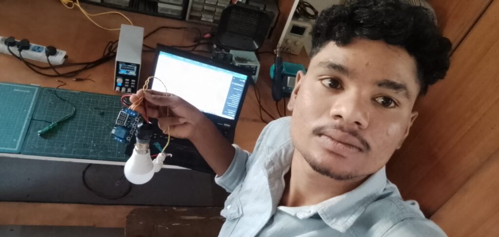
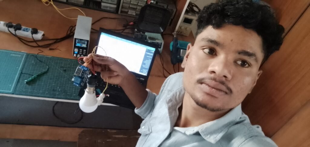
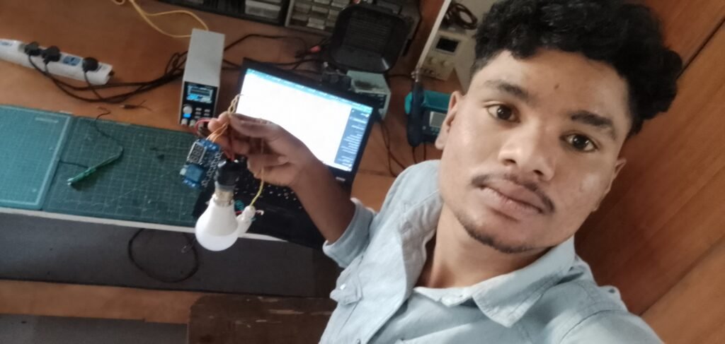
(22) LCD DISPALY TESTING CODE WITH NAME SHOW SO VERY BEAUTIFULL.
Materials List ;
- Arduino uno and then lcd display board .
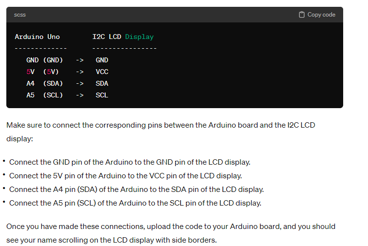
UPLOAD THE CODE ;
include
include
// Set the LCD address
define I2C_ADDR 0x27
LiquidCrystal_I2C lcd(I2C_ADDR, 16, 2);
// Your name
const char* name = ” Shankar Sai”; // Change “Shankar Sai” to your name
void setup() {
// Initialize the LCD
lcd.begin();
// Turn on the backlight
lcd.backlight();
}
void loop() {
// Display name with borders
displayWithNameAndBorder();
// Scroll name horizontally
scrollName();
// Delay for readability
delay(200);
}
// Function to display the name with side borders
void displayWithNameAndBorder() {
lcd.clear(); // Clear the LCD screen
// Print left border
lcd.setCursor(0, 0);
lcd.print(“….”);
// Print name
lcd.setCursor(1, 0);
lcd.print(name);
// Print right border
int nameLength = strlen(name);
lcd.setCursor(nameLength + 1, 0);
lcd.print(“….”);
}
// Function to scroll the name horizontally
void scrollName() {
static int offset = 0;
int nameLength = strlen(name);
// Shift the name one position to the left
for (int i = 0; i < 16; i++) {
lcd.scrollDisplayLeft();
delay(500); // Adjust delay to control scrolling speed
}
// Reset offset if the entire name has been scrolled
if (++offset >= nameLength + 16) {
offset = 0;
}
}
VIDEO;
