
In this post we are going to construct an automatic school bell/college bell system using Arduino, 16 x 2 display and real time clock module. You can program this project to ring the bell up to 16 times a day at your preferred hour and minute. The length of the bell ring can be programmed in seconds.
Gone are the days, when a peon in a school rang the bell “tin tin tin” and the students ran out of the school entrance with flying colors. Some may get even happier when the peon rang the last bell few minutes earlier.
This was the scenario 15 to 20 years ago, but now all the schools and colleges strictly time bound and the bells are automated.
Author’s quick childhood / teenage hood remember:
During my primary and secondary school the digital watch which I wore was synchronized with school’s bell system with 1 second precision.
I would yell “the bell is going to ring in 5 seconds” after the bell rang all students stare at me with surprise, this happens almost every day. On some day I and my close friends start count down 10, 9, 8, 7…..before the last bell.
All my friends say it is a magic wrist watch, but they didn’t realize one simple fact that the school bell was automated. LOL!!
We are going to make one such school/college bell using Arduino.
Display to Arduino Connection
The display to Arduino connections are slightly different from what we wire them usually, the pins 9, 8, 7, 6, 5 and 4 used here. The pin number 2 and 3 are used as hardware interrupt via push buttons.

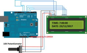
Use the 10K potentiometer for adjusting the contrast for the display.
Arduino school bell LCD
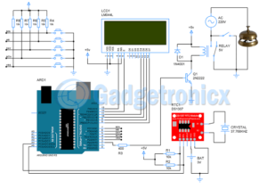
Automatic School / College Bell System Using Arduino
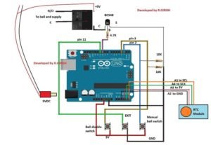
Detailed Information Regarding Bell and Relay Connections:
school bell timer circuit with Arduino
UPDATE: A5 to SCL and A4 to SDA (Not A4 to SCK)
Real Time Clock Module
The Real time clock module keeps the track of the time even after long power-cut. A 9V relay is provided for switching the bell on and off.
Please connect a 1N4007 diode in reverse bias across the relay (which is not shown in the schematic) which will absorbs harmful high voltage back EMF from relay.
Power the circuit using a 9V / 500mA wall adapter.
Three push buttons are provided one for manually operating the bell during some situation. Pressing the “exit” button will stop the bell after ringing the bell manually.
The “bell disable button” will disable the bell for ever. To re-enable the bell press the “Exit” button.
How to set time to RTC module:
Download the RTC library:
Link: github.com/PaulStoffregen/DS1307RTC
—————————————————————–
Download timeLib.h:
github.com/PaulStoffregen/Time
——————————————————————
Upload the Program
Upload the program below which will set the time to RTC
//—————————————————-//
#include
#include
#include
int P=A3; //Assign power pins for RTC
int N=A2;
const char *monthName[12] = {
“Jan”, “Feb”, “Mar”, “Apr”, “May”, “Jun”,
“Jul”, “Aug”, “Sep”, “Oct”, “Nov”, “Dec”
};
tmElements_t tm;
void setup() {
pinMode(P,OUTPUT);
pinMode(N,OUTPUT);
digitalWrite(P,HIGH);
digitalWrite(N,LOW);
bool parse=false;
bool config=false;
// get the date and time the compiler was run
if (getDate(__DATE__) && getTime(__TIME__)) {
parse = true;
// and configure the RTC with this info
if (RTC.write(tm)) {
config = true;
}
}
Serial.begin(9600);
while (!Serial) ; // wait for Arduino Serial Monitor
delay(200);
if (parse && config) {
Serial.print(“DS1307 configured Time=”);
Serial.print(__TIME__);
Serial.print(“, Date=”);
Serial.println(__DATE__);
} else if (parse) {
Serial.println(“DS1307 Communication Error :-{“);
Serial.println(“Please check your circuitry”);
} else {
Serial.print(“Could not parse info from the compiler, Time=\””);
Serial.print(__TIME__);
Serial.print(“\”, Date=\””);
Serial.print(__DATE__);
Serial.println(“\””);
}
}
void loop() {
}
bool getTime(const char *str)
{
int Hour, Min, Sec;
if (sscanf(str, “%d:%d:%d”, &Hour, &Min, &Sec) != 3) return false;
tm.Hour = Hour;
tm.Minute = Min;
tm.Second = Sec;
return true;
}
bool getDate(const char *str)
{
char Month[12];
int Day, Year;
uint8_t monthIndex;
if (sscanf(str, “%s %d %d”, Month, &Day, &Year) != 3) return false;
for (monthIndex = 0; monthIndex = 12) return false;
tm.Day = Day;
tm.Month = monthIndex + 1;
tm.Year = CalendarYrToTm(Year);
return true;
}
//—————————————————-//
After uploading the code, open the serial monitor, it will say that the time is set.
Once the above step is accomplished successfully move on to next.
Now upload the below code to Arduino.
Main program Code:
//————Program developed by R.GIRISH————//
#include
#include
#include
#include
#include
LiquidCrystal lcd(9, 8, 7, 6, 5, 4);
int i = 0;
int H = 0;
int M = 0;
int S = 0;
int setting_value;
const int bell = 10;
const int P = A3;
const int N = A2;
const int setting_address = 0;
const int over_ride_off = 11;
boolean bell_status = true;
boolean Over_ride = true;
//——————- Set Bell Timings from hours 1 to 23 hrs ——————-//
//—- 1st bell ——//
const int h1 = 0; //hours
const int m1 = 0; //Minutes
//—- 2nd bell ——//
const int h2 = 0;
const int m2 = 0;
//—- 3rd bell ——//
const int h3 = 0;
const int m3 = 0;
//—- 4th bell ——//
const int h4 = 0;
const int m4 = 0;
//—- 5th bell ——//
const int h5 = 0;
const int m5 = 0;
//—- 6th bell ——//
const int h6 = 0;
const int m6 = 0;
//—- 7th bell ——//
const int h7 = 0;
const int m7 = 0;
//—- 8th bell ——//
const int h8 = 0;
const int m8 = 0;
//—- 9th bell ——//
const int h9 = 0;
const int m9 = 0;
//—- 10th bell ——//
const int h10 = 0;
const int m10 = 0;
//—- 11th bell ——//
const int h11 = 0;
const int m11 = 0;
//—- 12th bell ——//
const int h12 = 0;
const int m12 = 0;
//—- 13th bell ——//
const int h13 = 0;
const int m13 = 0;
//—- 14th bell ——//
const int h14 = 0;
const int m14 = 0;
//—- 15th bell ——//
const int h15 = 0;
const int m15 = 0;
//—- 16th bell ——//
const int h16 = 0;
const int m16 = 0;
//————— bell ring lenght in seconds ——-//
const int Lenght = 3; //in seconds
//————————– ————————-//
void setup()
{
lcd.begin(16, 2);
pinMode(P, OUTPUT);
pinMode(N, OUTPUT);
pinMode(bell, OUTPUT);
pinMode(over_ride_off, INPUT);
digitalWrite(P, HIGH);
digitalWrite(N, LOW);
digitalWrite(over_ride_off, HIGH);
attachInterrupt(0, over_ride, RISING);
attachInterrupt(1, bell_setting, RISING);
if (EEPROM.read(setting_address) != 1)
{
bell_setting();
}
}
void loop()
{
tmElements_t tm;
lcd.clear();
if (RTC.read(tm))
{
H = tm.Hour;
M = tm.Minute;
S = tm.Second;
lcd.setCursor(0, 0);
lcd.print(“TIME:”);
lcd.print(tm.Hour);
lcd.print(“:”);
lcd.print(tm.Minute);
lcd.print(“:”);
lcd.print(tm.Second);
lcd.setCursor(0, 1);
lcd.print(“DATE:”);
lcd.print(tm.Day);
lcd.print(“/”);
lcd.print(tm.Month);
lcd.print(“/”);
lcd.print(tmYearToCalendar(tm.Year));
} else {
if (RTC.chipPresent())
{
lcd.setCursor(0, 0);
lcd.print(“RTC stopped!!!”);
lcd.setCursor(0, 1);
lcd.print(“Run SetTime code”);
} else {
lcd.clear();
lcd.setCursor(0, 0);
lcd.print(“Read error!”);
lcd.setCursor(0, 1);
lcd.print(“Check circuitry!”);
}
}
if (EEPROM.read(setting_address) == 1)
{
if (H == 0 && M == 0 && S == 0)
{
digitalWrite(bell, LOW);
}
if (H == h1 && M == m1 && S == 0)
{
for (i = 0; i < Lenght; i++)
{
digitalWrite(bell, HIGH);
delay(1000);
}
digitalWrite(bell, LOW);
i = 0;
}
if (H == h2 && M == m2 && S == 0)
{
for (i = 0; i < Lenght; i++)
{
digitalWrite(bell, HIGH);
delay(1000);
}
digitalWrite(bell, LOW);
i = 0;
}
if (H == h3 && M == m3 && S == 0)
{
for (i = 0; i < Lenght; i++)
{
digitalWrite(bell, HIGH);
delay(1000);
}
digitalWrite(bell, LOW);
i = 0;
}
if (H == h4 && M == m4 && S == 0)
{
for (i = 0; i < Lenght; i++)
{
digitalWrite(bell, HIGH);
delay(1000);
}
digitalWrite(bell, LOW);
i = 0;
}
if (H == h5 && M == m5 && S == 0)
{
for (i = 0; i < Lenght; i++)
{
digitalWrite(bell, HIGH);
delay(1000);
}
digitalWrite(bell, LOW);
i = 0;
}
if (H == h6 && M == m6 && S == 0)
{
for (i = 0; i < Lenght; i++)
{
digitalWrite(bell, HIGH);
delay(1000);
}
digitalWrite(bell, LOW);
i = 0;
}
if (H == h7 && M == m7 && S == 0)
{
for (i = 0; i < Lenght; i++)
{
digitalWrite(bell, HIGH);
delay(1000);
}
digitalWrite(bell, LOW);
i = 0;
}
if (H == h8 && M == m8 && S == 0)
{
for (i = 0; i < Lenght; i++)
{
digitalWrite(bell, HIGH);
delay(1000);
}
digitalWrite(bell, LOW);
i = 0;
}
if (H == h9 && M == m9 && S == 0)
{
for (i = 0; i < Lenght; i++)
{
digitalWrite(bell, HIGH);
delay(1000);
}
digitalWrite(bell, LOW);
i = 0;
}
if (H == h10 && M == m10 && S == 0)
{
for (i = 0; i < Lenght; i++)
{
digitalWrite(bell, HIGH);
delay(1000);
}
digitalWrite(bell, LOW);
i = 0;
}
if (H == h11 && M == m11 && S == 0)
{
for (i = 0; i < Lenght; i++)
{
digitalWrite(bell, HIGH);
delay(1000);
}
digitalWrite(bell, LOW);
i = 0;
}
if (H == h12 && M == m12 && S == 0)
{
for (i = 0; i < Lenght; i++)
{
digitalWrite(bell, HIGH);
delay(1000);
}
digitalWrite(bell, LOW);
i = 0;
}
if (H == h13 && M == m13 && S == 0)
{
for (i = 0; i < Lenght; i++)
{
digitalWrite(bell, HIGH);
delay(1000);
}
digitalWrite(bell, LOW);
i = 0;
}
if (H == h14 && M == m14 && S == 0)
{
for (i = 0; i < Lenght; i++)
{
digitalWrite(bell, HIGH);
delay(1000);
}
digitalWrite(bell, LOW);
i = 0;
}
if (H == h15 && M == m15 && S == 0)
{
for (i = 0; i < Lenght; i++)
{
digitalWrite(bell, HIGH);
delay(1000);
}
digitalWrite(bell, LOW);
i = 0;
}
if (H == h16 && M == m16 && S == 0)
{
for (i = 0; i < Lenght; i++)
{
digitalWrite(bell, HIGH);
delay(1000);
}
digitalWrite(bell, LOW);
i = 0;
}
}
delay(1000);
}
void over_ride()
{
lcd.clear();
while (Over_ride)
{
digitalWrite(bell, HIGH);
lcd.setCursor(0, 0);
lcd.print("Press Exit to");
lcd.setCursor(0, 1);
lcd.print("Stop the bell!!!");
if (digitalRead(over_ride_off) == LOW)
{
Over_ride = false;
digitalWrite(bell, LOW);
}
}
Over_ride = true;
}
void bell_setting()
{
setting_value = 0;
EEPROM.write(setting_address, setting_value);
lcd.clear();
while (bell_status)
{
lcd.setCursor(0, 0);
lcd.print("Bell is Disabled");
lcd.setCursor(0, 1);
lcd.print("Press Exit.");
if (digitalRead(over_ride_off) == LOW)
{
bell_status = false;
}
}
bell_status = true;
setting_value = 1;
EEPROM.write(setting_address, setting_value);
}
//————Program developed by R.GIRISH————//
After uploading the above code you should see the time in hours on the display.
That concludes the program code.
How to use this Automatic bell system:
Do this with completed hardware setup.
1. Upload the “time setting” code first and open the serial monitor.
2. In the main program set the time at which the relay needs to be triggered here.
//—- 1st bell ——//
const int h1 = 0; //hours
const int m1 = 0; //Minutes
//—- 2nd bell ——//
const int h2 = 0;
const int m2 = 0;
//—- 3rd bell ——//
const int h3 = 0;
const int m3 = 0;
//—- 4th bell ——//
const int h4 = 0;
const int m4 = 0;
• Set h1 in hours from 1 to 23 hours and m1 in minutes from 0 to 59.
• Same for h1 to h16 and m1 to m16.
• If you want to disable some bell leave value h = 0 and m = 0 for example: h5 = 0 and m5 = 0, zero will disable that particular bell.
3. Set the time length for the bell to be turned on and off period, here:
//————— bell ring lenght in seconds ——-//
const int Lenght = 3; //in seconds
By default the value is set for 3 seconds. When the set time is arrived the relay will be turned on for 3 seconds and turns off. Change this if you need.
4. Upload the modified code to Arduino.
5. To disable the bell press “bell disable button”. To re-enable press “Exit” button.
6. To ring the bell manually press the “manual bell switch” and to stop the bell press “exit”.


