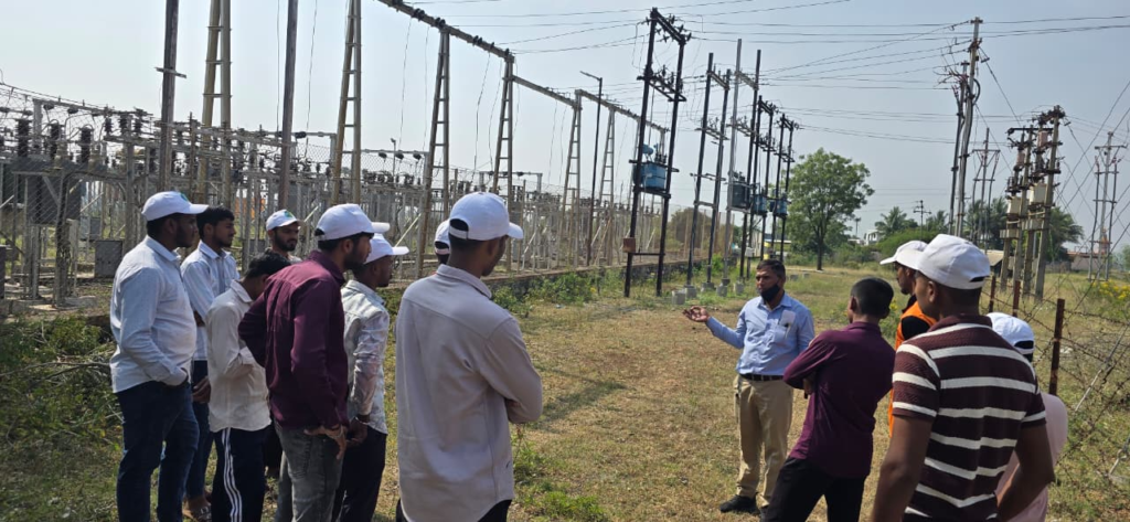
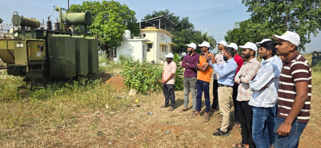
1. How an MSEB substation works


9
A substation receives electrical power at a particular voltage, controls and protects the supply, and transfers it to other lines at the required voltage.
Incoming supply
High-voltage line from the transmission network
Circuit breaker and isolator
Switching, fault interruption and safe isolation
Busbar and protection system
Power distribution and fault monitoring
Power transformer
Steps voltage up or down as required
Outgoing feeders
Supply to distribution networks and consumers
The exact arrangement depends on whether you are visiting a 33/11 kV, 132/33 kV, or another type of substation.
2. Important equipment at the substation
Observe these components during your visit and ask the substation engineer about their ratings and operation.

1. Circuit Breaker (CB / VCB)
- Switches electrical circuits ON and OFF.
- Trips automatically when protection detects a fault.
- A VCB extinguishes the electrical arc inside a vacuum interrupter.

2. Power Transformer
- Changes voltage from one level to another.
- Uses electromagnetic induction.
- Oil-filled transformers use oil for insulation and cooling.

3. Isolator
- Provides isolation for maintenance.
- Normally operated only under the conditions specified by the switching procedure; it is not designed to interrupt normal load current.

4. Protection Relay
- Monitors electrical quantities.
- Detects faults such as overcurrent and earth faults.
- Sends a trip command to the circuit breaker.

5. CT and PT/VT
- CT means Current Transformer.
- PT/VT means Potential/Voltage Transformer.
- They provide suitable signals for metering and protection.
3. MACB working process
One possible identification is MACB12, a model designation used for a vacuum circuit breaker with a magnetic actuator. A manual for that model describes magnetic-actuator opening and closing. However, this does not establish that every breaker called MACB has the same meaning or design.
Capacitor
If this is the equipment you saw, its operating sequence is generally:
Step 1 — Normal condition
The breaker contacts are closed and current flows through the circuit.
Step 2 — Fault detection
A protection relay detects an abnormal condition, such as excessive current or an earth fault.
Step 3 — Tripping
The trip circuit activates the breaker mechanism. The contacts separate and the arc is extinguished in the interrupter.
Step 4 — Fault isolation
The affected circuit is disconnected, and the protection/control system indicates the breaker status.
Closing and resetting must follow the substation’s authorized switching procedure. Never operate a breaker or isolator yourself during the visit.
4. Information to record during your visit
- Substation voltage level: for example, 33/11 kV.
- Transformer capacity: kVA or MVA.
- Breaker type: VCB, SF₆, oil, or another type.
- Breaker make, model and rated voltage.
- Rated current in amperes and breaking capacity in kA.
- Control supply voltage and operating mechanism.
- Protection relay type and trip indication.
- Incoming and outgoing feeder details.
5. Safety precautions
- Stay with the authorized engineer or staff member.
- Do not touch electrical panels, busbars, cables or equipment.
- Keep behind marked safety barriers.
- Do not take photographs unless permission is given.
- Follow all site instructions and required PPE rules.